It is cold, dark, dank and gloomy out, which means it is dynamo season again. 'Tis the season to make sure that all the wires are connected nicely to all your lights. I confess that in the past I have been a bit paranoid about bad wiring and unreliable lights; this means for many years I have preferred to open up my lamps and solder wires to the relevant parts of the lamps permanently. If I can manage it, the only breakable connections in a good dynamo light system might be at the generator itself; additional connections are just extra places where faults can develop, and are best avoided.
The above approach has served me well. But this doesn't make for quick or easy installation. Nor does it allow for quick and easy lamp replacements in the event of breakage, failure, or just wanting to mess about and try different things out.
After connecting the headlight to the generator, the most common wiring task in a typical hub generator system is connecting the rear light to the headlight. It is absolutely vital that this connection is made as reliable as possible; if your rear light goes out as you ride you may not notice and this leaves you vulnerable to dozy drivers. Most commonly the connections to the rear light are made at one or both ends using 2.8mm blade terminals; male in the lamp housings, female on the wire ends. The best way of making these connections is probably to use good quality crimp terminals on the wires. Some B&M lights come with a length of wire for the rear light that is correctly terminated at one end. But you might need one a different length or to have the terminals at both ends.
Since I happen to possess suitable crimping tools for these terminals, I thought it remiss of me not to break them out and use them.
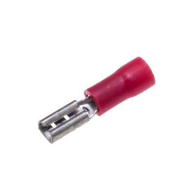
The most common type of crimp terminal is probably the 'Engex' sort that has a red, blue, or yellow sleeve around the strain relief part of the connection. These terminals are crimped over the coloured sleeve and can provide a good connection in many instances.
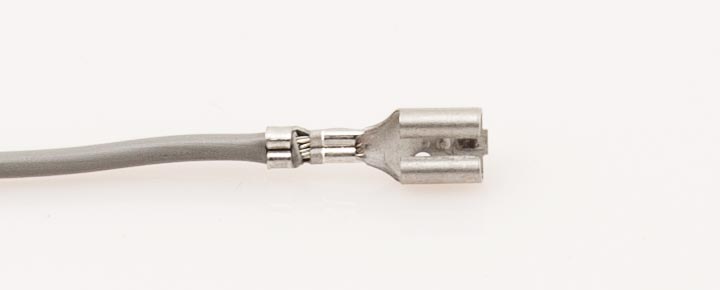
Terminals can have a full insulating sleeve or (as above) not. 2.8mm female blade type shown.
However inevitably there are problems; the 'red' type is the smallest size commonly available yet it will accommodate 1.5mm^2 conductors. Which is a bit OTT for running a rear light which takes 100mA tops. It is not certain that the skinny wires used in dynamo lights will be crimped well at all. The strain relief isn't as good as many terminals. You can't easily inspect the quality of the crimp after it has been made (you can't see where the insulation ends because it is hidden). You can't easily apply waterproofing (eg Vaseline or waxoyl) to an assembled connector. However the real show stopper for bicycles may be that the coloured sleeve is so fat it sometimes makes it impossible to fit the terminal to a lamp.
If you want to use these terminals you can make a reasonable job of it by crimping the terminals, cutting the red stuff off, inspecting the crimp better, and then using heat-shrink insulation on it.
Needless to say terminals of this sort are not used by B&M and other good lamp makers; they use better quality crimps which are made using more sophisticated tooling.
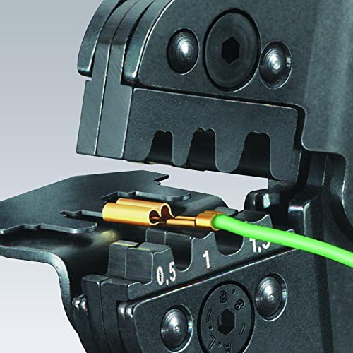
My best tool for this job is a Molex 69008-0953 crimp tool which I have had for years; it wasn't cheap when I bought it originally but I recently looked it up and was horrified at the current replacement cost; I am sure that there must be cheaper alternatives. Anyway, this tool is designed to crimp Molex type 2478 terminals to 18-24 AWG wires. It happens that there are many terminals (other than Molex-manufactured ones) which are compatible with this tool. These vary in design, material, plating, and whether or not they come with insulation or whether you are meant to use heat shrink. They vary in cost and quality, from pennies each to a more significant cost per item. The ones I have used here were not expensive ones.
- phosphor bronze (L) and brass (R) terminals
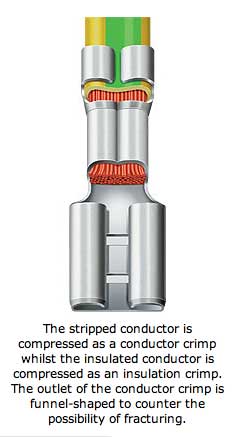
The terminals are crimped at both conductor (electrical connection) and insulator (for strain relief) by two sets of jaws, in a single operation.
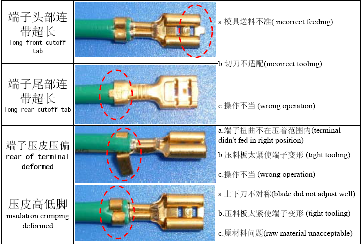
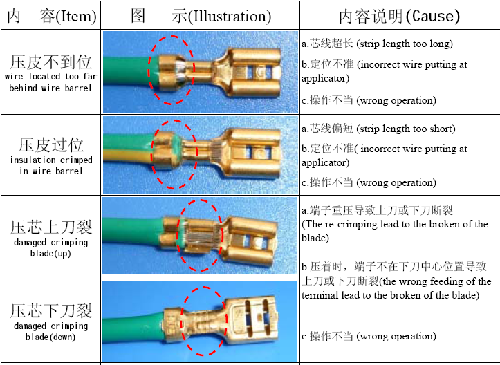
I have taken a series of photographs in which I have tried to show how crimping works and what might constitute a reasonably acceptable crimp quality.
- simple figure-8 bell wire for the rear light
- use of automatic wire stripper is important when there are not many strands in the wire
- nice clean strip, no broken strands
tbc