My new project....
-
rogerzilla
- Posts: 2914
- Joined: 9 Jun 2008, 8:06pm
Re: My new project....
Ah yes, there is something funny going on with those bellows. I thought they had just become detached at the top (they slot into a groove between the crown race and the lower bush retaining cup). Early bikes were, I think, 1" at the top and bottom of the headset. Later bikes use a totally unique size at the bottom, for which spares are long gone. It is close to 1 1/4" (Fisher Evolution) cup size, and could potentially be reamed out, but Evolution isn't much more common.
Re: My new project....
Nothing wrong with the bellows, I believe. They were seated properly when I viewed the bike. I pulled them back to check the state of the compression splines and they needed something more than my clumsy fingers to reseat them.rogerzilla wrote: ↑20 May 2022, 9:19pm Ah yes, there is something funny going on with those bellows. I thought they had just become detached at the top (they slot into a groove between the crown race and the lower bush retaining cup).
The older I get the more I’m inclined to act my shoe size, not my age.
-
rogerzilla
- Posts: 2914
- Joined: 9 Jun 2008, 8:06pm
Re: My new project....
They don't look like the narrow type but it may just be the way they're compressed.
The normal bellows are still available new - just - from Moulton Preservation at events but I don't think anyone has tried to remanufacture the narrow ones as demand would be almost zero - they are super rare. Of course, automotive steering rack bellows of suitable diameter can be made to fit, using zipties if necessary.
The normal bellows are still available new - just - from Moulton Preservation at events but I don't think anyone has tried to remanufacture the narrow ones as demand would be almost zero - they are super rare. Of course, automotive steering rack bellows of suitable diameter can be made to fit, using zipties if necessary.
Re: My new project....
Ah, I see where you are coming from. I would imagine they are not original given their condition so yes, probably not period correct.
The older I get the more I’m inclined to act my shoe size, not my age.
-
simonineaston

- Posts: 8062
- Joined: 9 May 2007, 1:06pm
- Location: ...at a cricket ground
Re: My new project....
I thought about this excellent website the other day and mused that it was no longer available, however I'm pleased to see that I was wrong. It's got some great step-by-step guides to some elements of F frame renovation - see here
Edit: the linked page makes reference to Michael Woolf at Moulton Preservation who we lost earlier in the year.
Edit: the linked page makes reference to Michael Woolf at Moulton Preservation who we lost earlier in the year.
S
(on the look out for Armageddon, on board a Brompton nano & ever-changing Moultons)
(on the look out for Armageddon, on board a Brompton nano & ever-changing Moultons)
Re: My new project....
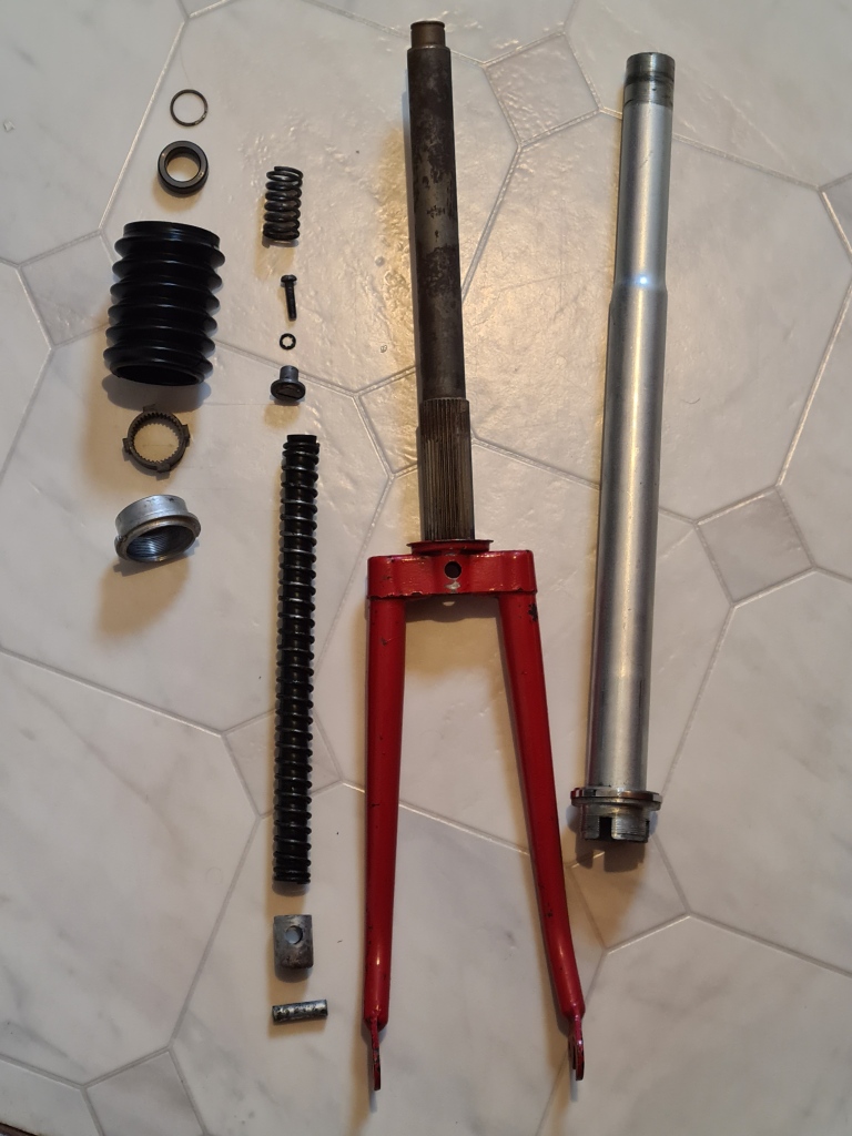
I'm refurbishing my moulton. A recent acquisition dated 1965. It's a mark 2 with the beafed up rear forks and integral stand.
I've hit a problem with the front forks. I've removed the bottom cup and brake sleeve. Loosened the splined screw. Theres a 5mm movement on the suspension. The fork goes up and down but only by 5 mm and feels like it's hitting a solid stop. At the top end there is no Philips screw but a 1/2" af nut partially screwed onto a threaded rod, the threaded rod, bolt or whatever goes further down below and is now hiden. This nut is just above the change in diameter on the outer casing above the recess for the Philips screw In my mates. I can easily turn the nut but it's seized solid on the threaded rod so both turn together. It's connected to the lower forks as they both go up and down the same 5mm. The suspension is not functioning either but I can compress the rubber insert and spring by using a wooden dowel to push it down about 15mm.
I'm at a loss to work out what's going on here. Is this a factory delivered item or has someone bodged it? BTW the stem was seized in the forks, very rusty but I managed to free it off and remove it.
I can't see a straitforward simple way to progress. Anyone able to offer any advice. Possible way forward as a last resort would be to drill the nut centre until it drops off.
Not sure I have a long enough drill and how do I stop the nut rotating.
At the last count:- Peugeot 531 pro, Dawes Discovery Tandem, Dawes Kingpin X3, Raleigh 20 stowaway X2, 1965 Moulton deluxe, Falcon K2 MTB dropped bar tourer, Rudge Bi frame folder, Longstaff trike conversion on a Giant XTC 840 
Re: My new project....
This is what it should look like, im assuming mine has a bolt which holds the rebound spring in place. I may try and pull the lower rubber and spring unit out and see whats up inside.rjb wrote: ↑7 May 2023, 6:02pm I'm refurbishing my moulton. A recent acquisition dated 1965. It's a mark 2 with the beafed up rear forks and integral stand.
I've hit a problem with the front forks. I've removed the bottom cup and brake sleeve. Loosened the splined screw. Theres a 5mm movement on the suspension. The fork goes up and down but only by 5 mm and feels like it's hitting a solid stop. At the top end there is no Philips screw but a 1/2" af nut partially screwed onto a threaded rod, the threaded rod, bolt or whatever goes further down below and is now hiden. This nut is just above the change in diameter on the outer casing above the recess for the Philips screw In my mates. I can easily turn the nut but it's seized solid on the threaded rod so both turn together. It's connected to the lower forks as they both go up and down the same 5mm. The suspension is not functioning either but I can compress the rubber insert and spring by using a wooden dowel to push it down about 15mm.
I'm at a loss to work out what's going on here. Is this a factory delivered item or has someone bodged it? BTW the stem was seized in the forks, very rusty but I managed to free it off and remove it.
I can't see a straitforward simple way to progress. Anyone able to offer any advice. Possible way forward as a last resort would be to drill the nut centre until it drops off.
Not sure I have a long enough drill and how do I stop the nut rotating.
At the last count:- Peugeot 531 pro, Dawes Discovery Tandem, Dawes Kingpin X3, Raleigh 20 stowaway X2, 1965 Moulton deluxe, Falcon K2 MTB dropped bar tourer, Rudge Bi frame folder, Longstaff trike conversion on a Giant XTC 840
Re: My new project....
Some subtle differences to this arrangement.  Which has what's called a Stool Is this item what I'm seeing in mine with the 1/2" nut when viewed down the steerer tube. ???
At the last count:- Peugeot 531 pro, Dawes Discovery Tandem, Dawes Kingpin X3, Raleigh 20 stowaway X2, 1965 Moulton deluxe, Falcon K2 MTB dropped bar tourer, Rudge Bi frame folder, Longstaff trike conversion on a Giant XTC 840
-
simonineaston
- Posts: 8062
- Joined: 9 May 2007, 1:06pm
- Location: ...at a cricket ground
Re: My new project....
Unfortunately, I can't cast any helpful light on the situation as the machine in question came & went without me doing any work on it. However I'll guess that someone has replaced the original rebound stop retaining screw (which were BA threadform) with a piece of stud and on assembly, used a nut at the top end of the piece of stud. It can often be the case that these small bolts are deformed by previous attempts to service the fork and this may be a previous owner's attempt at a 'work-around'.At the top end there is no Philips screw but a 1/2" af nut partially screwed onto a threaded rod, the threaded rod, bolt or whatever goes further down below and is now hiden.
It may be that once the nut is removed, the rest of the fork components will come apart as usual. A lot depends on how the stud is retained (if at all) in the rebound stop. I have a vague recollection that the rebound stop has a slot cut in its lower end... if you can remove the rubber spring, you may be able to stop the rebound stop rotating if you have a long enough flat blade screwdriver. I've heard of folk using a suitable long thin screw inserted into the base of the rubber spring to draw them out.
(all the component names are taken from the diagram in an earlier post)
S
(on the look out for Armageddon, on board a Brompton nano & ever-changing Moultons)
(on the look out for Armageddon, on board a Brompton nano & ever-changing Moultons)
-
simonineaston
- Posts: 8062
- Joined: 9 May 2007, 1:06pm
- Location: ...at a cricket ground
Re: My new project....
Actually, I'm being dim - the metal coil spring / rubber spring pair is retained by the brake bush / spring abutment combo...
S
(on the look out for Armageddon, on board a Brompton nano & ever-changing Moultons)
(on the look out for Armageddon, on board a Brompton nano & ever-changing Moultons)
Re: My new project....
Thanks Simon,
I managed to remove the spring and rubber sleeve with a bit of levering. There is a slot in the bottom of the rebound stop but even holding it with a long screwdriver I was unable to release it. I cleaned everything as best I could and lubricated the lower bush, splined shaft and suspension springs and rubber and put everything back together. The suspension now works but feels a bit gritty. May ease up in service.
BTW Dave's rear forks were cracked. 2 cracks eminating from the weld which looks like a weld defect as it's not actually taken on the fork.
At the last count:- Peugeot 531 pro, Dawes Discovery Tandem, Dawes Kingpin X3, Raleigh 20 stowaway X2, 1965 Moulton deluxe, Falcon K2 MTB dropped bar tourer, Rudge Bi frame folder, Longstaff trike conversion on a Giant XTC 840
-
rogerzilla
- Posts: 2914
- Joined: 9 Jun 2008, 8:06pm
Re: My new project....
The rebound spring stop with the large slot is tabbed and designed NOT to rotate, so you won't get it out by unscrewing it!
I think you just need to keep turning that 1/2" nut now the rubber spring is out. That's what was holding it together, rusted to the inner steerer.
The correct screw is 2BA Philips pan head, but they're no longer available, so you can use 2BA Posidriv or 2BA slotted if you have a suitable long screwdriver. The length is quite critical and I can measure one for you if you like.
That is where the rear forks always crack. Design fault, stress riser at the base of the crescent cup.
Last edited by rogerzilla on 10 May 2023, 8:27pm, edited 1 time in total.
-
simonineaston
- Posts: 8062
- Joined: 9 May 2007, 1:06pm
- Location: ...at a cricket ground
Re: My new project....
...from Moultonbuzz https://www.moultonbuzz.com/preservation/
- screenshot of web page
S
(on the look out for Armageddon, on board a Brompton nano & ever-changing Moultons)
(on the look out for Armageddon, on board a Brompton nano & ever-changing Moultons)
Re: My new project....
My rebound stop rotates freely. I was using the screwdriver to hold it still whilst attempting to turn the 1/2 nut at the top. It's seized solidly together so I can't separate them. The rebound stop rotates with the nut inside the fork column. I'm realising now that it's been bodged by a previous owner. It's not been ridden far either as the John Bull no 25 brake blocks are hardly worn.rogerzilla wrote: ↑10 May 2023, 8:21pm The rebound spring stop with the large slot is tabbed and designed NOT to rotate, so you won't get it out by unscrewing it!
I think you just need to keep turning that 1/2" nut now the rubber spring is out. That's what was holding it together, rusted to the inner steerer.
The correct screw is 2BA Philips pan head, but they're no longer available, so you can use 2BA Posidriv or 2BA slotted if you have a suitable long screwdriver. The length is quite critical and I can measure one for you if you like.
That is where the rear forks always crack. Design fault, stress riser at the base of the crescent cup.
20220607_182618.jpg
Next course of action would be to drill out the nut from above but I will hang fire and see how it feels on the road. Thanks for the info, if you have the 2ba bolt measurement that would be great. I have some 2 ba brass bolts somewhere in my man cave.
Thanks Simon, I'll pass this on to David.
Last edited by rjb on 21 May 2023, 7:24pm, edited 1 time in total.
At the last count:- Peugeot 531 pro, Dawes Discovery Tandem, Dawes Kingpin X3, Raleigh 20 stowaway X2, 1965 Moulton deluxe, Falcon K2 MTB dropped bar tourer, Rudge Bi frame folder, Longstaff trike conversion on a Giant XTC 840
-
rogerzilla
- Posts: 2914
- Joined: 9 Jun 2008, 8:06pm
Re: My new project....
I'll dig one out tomorrow and measure it.
I think Gary Hall only adds brass. The series 1 rear forks really need gussets to eliminate that stress riser. This is what Argos did with mine (and added an extra web for stiffness).
I think Gary Hall only adds brass. The series 1 rear forks really need gussets to eliminate that stress riser. This is what Argos did with mine (and added an extra web for stiffness).